DYI: sailboats + 3D print + electronics

Tag: yacht

  • Window Frames (Part II)

    Window Frames (Part II)

    Having a ready 3D model still requires preparation for printing, which is what a slicer is for. My first test prints were done using Creality Slicer, but I quickly switched to Ultimaker Cura.

    A major decision was choosing the filament. The basic version of Creality (without tent/enclosure) limited me to PLA and PETG. PLA is environmentally friendly (polylactide is generally obtained from corn flour) and easy to print. Unfortunately, it has low resistance to environmental influences and low temperature resistance. Attempts at sanding immediately melt the material. PETG, on the other hand, is difficult to paint.

    The initial idea was to use white PLA or PETG directly without any finishing. However, visible print imperfections, including visible printing lines, and the not quite matching color, forced the option of finishing.

    Ultimately, the choice fell on PLA. Painting should solve the moisture resistance issues, and the fact that the elements are white solves the temperature problem (black PLA exposed to the sun softens!). After a few attempts, the satisfactory final effect was achieved with:

    • Coating the print with a layer of epoxy primer.
      I used an epoxy primer spray, which is used in bodywork repairs. I used a local product, BOLL Epoxy Primer, but any similar product will do the job.
    • Sanding.
      I used foam paper with a grit of 200 and higher.
    • Painting.
      The print was painted with base automotive acrylic (as white was to be achieved) using a paint gun. The paint was purchased from a supplier supplying bodywork workshops.

    All prints used a 0.4mm nozzle and the default Cura profile for PLA: 0.12mm for final prints and 0.28 for draft with 20% infill. I used Spectrum PLA Pro Arctic White filament.

    Creality CR-10 busy printing window frame (aprox. 14 hours per part ).

    Prints

    Each frame was first printed in draft mode to ensure the prints fit well. In the draft version, some parts of the prints were “welded” using a 3D pen.

    Draft print. Only to verify dimensions and fit tolerance..

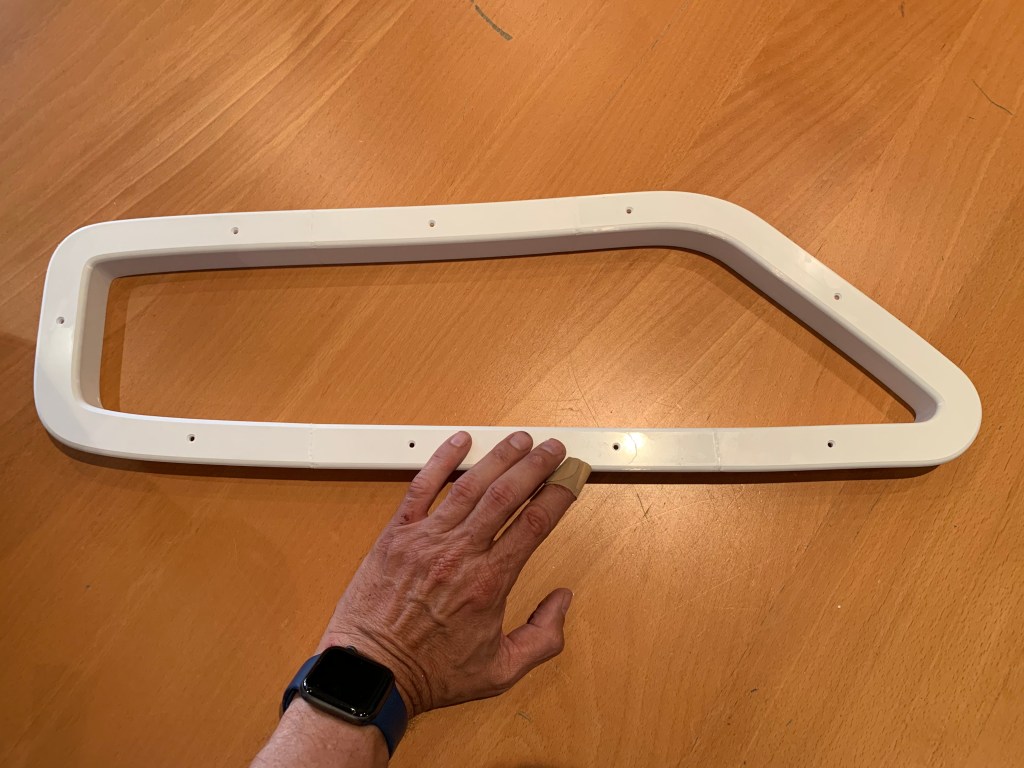
    The final print was glued with epoxy and underpinned at the joints. The prints were made “face down” to ensure a flat front surface with maximally limited 3D printing traces.

    Wooden original and 3D printed replacement. After gluing two parts but before epoxy priming and painting. Lighter, slimmer and giving bit more light.

    There was some work with sanding, polishing, and painting, but the final effect is rewarding. Now, more than 4 years later, the prints look the same as on the first day.

    • apply thing layer of expoxy for priming; the epoxy priming for car reapirs were used; is used local procuct BOLL epoxy primer but anything simillar will be good.
    • such layer can be then saned to achive a smooth ayer
    • final print was painted with acrylic car paint.
    Final. Acrylic painted

    An unpleasant surprise at the end

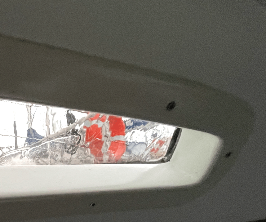
    Having finished the first frame for one side, I thought it would be enough to make a mirror copy for the other side. Unfortunately…

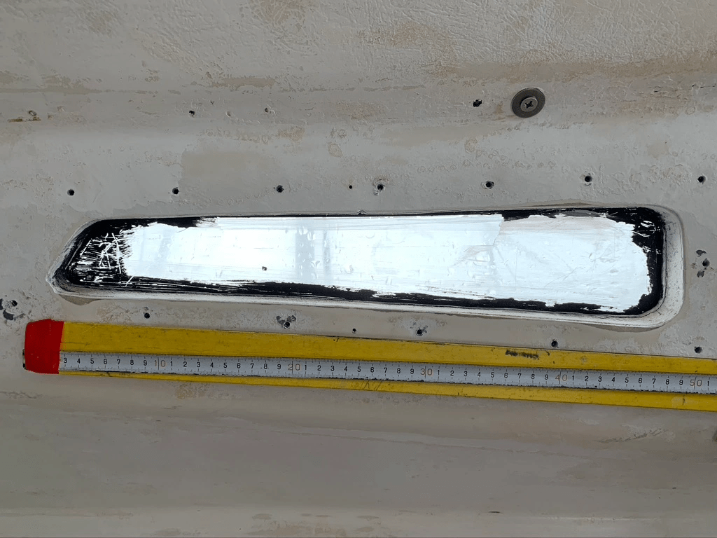
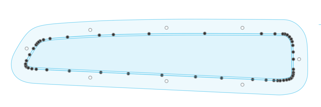
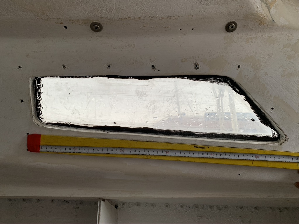
    Bostrom B31 was purchased by future owners in a DIY version. The company supplied the hull, while the equipment was done on their own. As a result, there are no two identical B31s. Since the finishing, including window openings, was not done at the shipyard, the cutouts are not exactly the same either. In the photos below, you can notice slight differences in the corner shapes and dimensions.

    Starboard window
    Port side window

    I had to go back to the drawing board and design the windows separately for the other side. Practice makes perfect, so this time it went smoothly.

    Window frames (Part I)

  • Window frames (Part I)

    Window frames (Part I)

    Intro

    It was the year 2020. I had to replace the window frames. The existing ones were so thick that they limited the amount of incoming light and simply looked bad. Moreover, they were so worn that they required repair anyway. The sailboat is not standard, and neither are its windows. Making custom aluminum frames turned out to be costly, and the delivery times were not encouraging. New wooden frames would have been too thick for technological reasons. So, the idea of using 3D printing came up. However, 3D printing is something I associate with small toys rather than practical prints. Moreover, the print size was definitely larger than any available printer could offer. Without completely rejecting the idea of aluminum frames, I decided to try 3D printing.

    After analyzing the market, I decided to buy a Creality CR-10 printer, which had a large enough working area (300x300x400mm) to print the frames in two parts. Moreover, it was cheap enough that a potential failure wouldn’t be financially painful. However, after the first two test prints, I destroyed the work plate. Fortunately, I found that IKEA LOTS mirrors, along with a bit of hairspray, perfectly replaced it.

    I had never used CAD. I am a software developer, and this world was completely foreign to me. Among the paid and free software options, I chose Autodesk Fusion 360. This program is free for home use. It turned out to be quite simple to learn (although I’m still learning!). 

    So, the equipment was assembled. It’s time to attempt designing and making the frames.

    Designing

    The shapes of the windows are irregular. Therefore, I took a photo of the window with a ruler attached, so that I could later import it into Fusion 360 as a Canvas and use the ruler for dimension calibration.

    Windows photo.

    Unfortunately, it turned out that perspective distortions (the photos had to be taken from a close distance) disqualified this solution.

    So, I attached A4 sheets to the opening and manually traced the shape. Calibration no longer required a ruler because after scanning, it was enough to set the scan height to the size of A4 (297mm) and precisely align both scans together.

    Scans in Fusion 360.

    Using Fusion 360 Sketch tools, I traced the scans, automatically adding a wide border and a border for the insert that will fit into the window’s hole.

    Canvas(scans) and Sketch(drawings) together.
    Sketch itself.

    Now it was enough to use Extrude to create a three-dimensional model (Body).

    Body and Sketch. Half of a model visible – model prepared to be printed in parts.

    After adding holes for screws and rounding edges, the model was ready for printing.

    Window Frames (Part II)

  • The beginning

    The beginning

    I bought a sailboat in 2018, a Bostrom 31 launched in 1976. We named her Growler. Of course, she required repairs and improvements immediately. Some of these needed to be done in a hangar with the help of professionals. However, I decided to do some of the work myself.

    Since I live in an apartment and don’t have a garage or workshop, woodworking was not an option. I thought I could use 3D printing. At the time, I mainly associated it with printing figurines and toy gadgets. I bought a Creality CR-10 and decided to dive into the deep end by starting my 3D printing adventure with making window frames approximately 70 by 26 cm in size.

    Over the years, more and more 3D prints appeared, and then small electronic projects were added. Quite a lot accumulated, and motivated by friendly sailors, I decided to start sharing them.